Axial movement of the shaft relative to the machine
housing in the area of the shaft opening through the housing wall, i. e. in the area of
the (mechanical) seal. Shaft displacement is either required for functional reasons (cf.
picture) or is
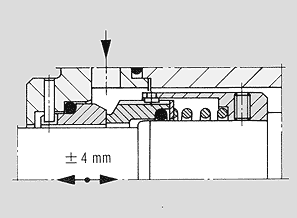
Single, balanced standard mechanical seal type NB in conformance with DIN 24 960

caused by unequal expansion of machine parts under alternating thermal loads. By making
design modification to the mechanical seal itself or to the mechanical seal's connections,
it is possible to compensate the shaft displacement in the area of the mechanical seal.
Shaft displacements up to +/-4 mm can be compensated by NU and NB type mechanical
seals in conformance with DIN 24 960 (figure) if the
proper steps are taken. Special mechanical seal designs (multiple spring-backing with
spring guide pins) can compensate shaft displacements of up to approximately 60 mm; generator seal. Bigger shaft displacements (currently
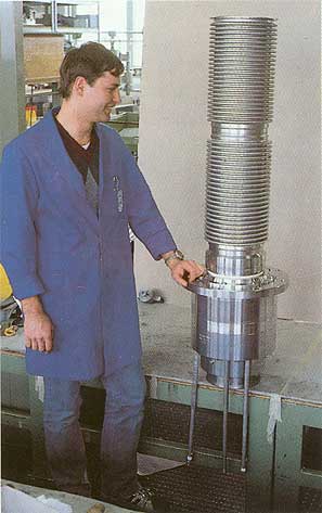
up to around 450 mm) are compensated by metal expansion joints that link the shaft
sleeve with the shaft (figure). The mechanical seal itself is unaffected by the shaft
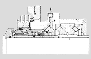
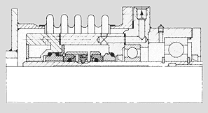
displacement. In the case of large-capacity horizontal vessels, in which – for
thermal reasons – the shaft displacement coincides with angular and radial distortion
of the vessel's face wall, the mechanical seal fixed on the shaft is provided in the seal
housing with an own bearing that follows the shaft movements (figure). The axial, radial
and angular movements are compensated by a metal bellows positioned between the seal
housing and the vessel's face wall. |
|

Double mechanical seal for balancing shaft displacement

Double mechanical seal with externally (top) and internally (bottom) pressurized metal
bellows for balancing the misalignment between shaft and vessel
 |


