| Circulation of the pumped medium | ||
| In pumps with single
mechanical seals it is customary to divert part of the pumped flow via the mechanical
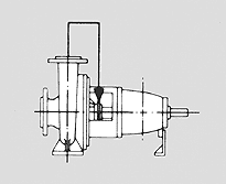
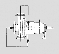
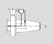
seal. Entry into (and exit out of) the stuffing box must take place in the area of the sliding faces . This measure is aimed at selective frictional heat transfer from the mechanical seal and lowering of the temperature at the mechanical seal, or the prevention of deposits. Standard systems of circulation: Arrangement outline: Circulation of liquid from the pressure connection to the mechanical seal chamber, and from the mechanical seal chamber to the suction connection.
To DIN ISO 5199 : |
||
 |
 |
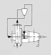 |
| No. 02 Circulation of liquid from the pressure connection to the mechanical seal chamber, and from the mechanical seal chamber to the suction connection of the pump | No. 03 (external), No. 07 (internal) Internal or external circulation with recycling to the suction connection of the pump | No. 04 With cyclone separator, contaminant line to suction connection of the pump |
| No. 05 With cyclone separator, external contaminant discharge | 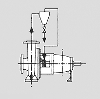 |
|
| To VDMA 24 297: |
||
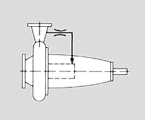
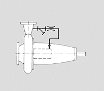
| for clean, cold pumped medium (No.6.1, 6.2) : | for clean, hot pumped medium(No. 6.3, 6.4) : | |
 |
 |
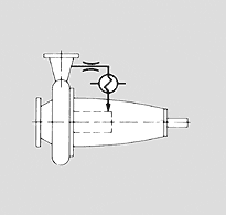 |
| No. 6.1 With throttle mechanism | No. 6.2 With contaminant trap and throttle mechanism | No. 6.3 With throttle mechanism and cooler |
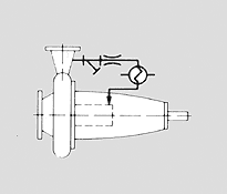
| for contaminated, cold pumped medium | for contaminated, hot pumped medium |
|
 |
 |
|
| No. 6.4 With contaminant trap, throttle mechanism and cooler | No. 6.6 With cyclone separator | No. 6.8 with cyclone separator and cooler |
To API 610 : ffor clean pumped medium : |
||
|
|
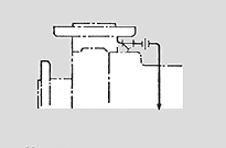 |
Plan No. 1 iIntegral (internal) recirculation from pump discharge to seal |
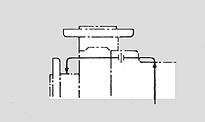
Plan No. 11 Recirculation from pump case through orifice to seal |
Plan No. 12 Recirculation from pump case through strainer and orifice to seal |
 |
 |
|
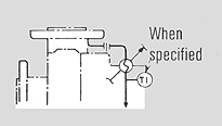
| Plan No. 13 Recirculation from seal chamber through orifice and back to pump suction | Plan No. 21 Recirculation from pump case through orifice and heat exchanger to seal | Plan No. 22 Recirculation from pump case through strainer, orifice, and heat exchanger to seal |
for contaminated pumped medium (No. 31, 41) : |
||
|
 |
Arrangement outline: The mechanical seal chamber is separated from the medium chamber by a throttle section. The latter prevents a vigorous exchange of medium between the seal and pump chamber, but enables pressure balancing and the supply of liquid as replacement for the mechanical seal leakage. |
Plan No. 31 Recirculation through cyclone separator delivering clean fluid to seal and fluid with solids back to pump suction |
Plan No. 41 mit Recirculation through cyclone separator delivering clean fluid through heat exchanger to seal and fluid with solids back to pump suction | |
| To DIN ISO 5199 : |
To VDMA 24 297 : |
To API 610 : |
| for clean, hot pumped medium : | for clean medium : |
|
|
 |
|
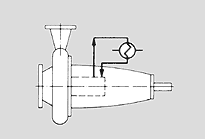
No. 06 Circulation of pumped medium by pumping system via heat exchanger and back to the stuffing box |
No. 6.5 Circulation of pumped medium by pumping mechanism through cooler and back to the mechanical seal |
Plan No. 23 Recirculation from seal with pumping ring through heat exchanger and back to seal |